Vehicle information
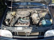
| Brand: | Ford |
| Model: | Fiesta |
| Engine: | 1.3 L |
| Engine code: | J6B |
| Cylinder count: | 4 |
| Fuel type: | Petrol |
| Motor management system: | FORD CFI EEC-IV |
Used equipment
Automotive Test Scope ATS5004D
4 channel automotive oscilloscope with differential inputsMeasure lead TP-C1812B
low noise differential BNC to banana measuring lead, 3 mBack Probe TP-BP85
thin and flexible back probeThe Automotive Test Scope ATS5004D is in this article also referred to as automotive oscilloscope, diagnosis oscilloscope and as lab scope.
Introduction
When troubleshooting intermittent problems, a good automotive oscilloscope is indispensable. It needs to have some specific features to help finding the cause of the problems. One of the features is the ability to perform a long measurement at a high sampling speed, triggered by a manual trigger button, capturing signals before and after the trigger moment.
Problem description
A Ford Fiesta with J6B engine was suffering occasional stuttering. The shop it was brought to did not have an oscilloscope, so they could not easily locate the source of the problem. They did replace some components, but the problem remained. Unable to solve the problem, they contacted GMTO for diagnosis assistance.
Measuring
When an engine occasionally holds back, there is usually a problem with injection or ignition. The best way to diagnose this, is to place a good automotive oscilloscope like the Automotive Test Scope ATS5004D in the car and connect it to an injection signal and an ignition signal. The scope needs to be setup to measure for a long time at a high sampling rate. A manual trigger button is used to trigger the oscilloscope to capture the signals and store them. It is even possible to view signals that were recorded before pressing the trigger button. This makes it possible to see how a problem situation develops. Once the lab scope is connected, it is just a matter of driving the car until the engine holds back and then pressing the trigger button.
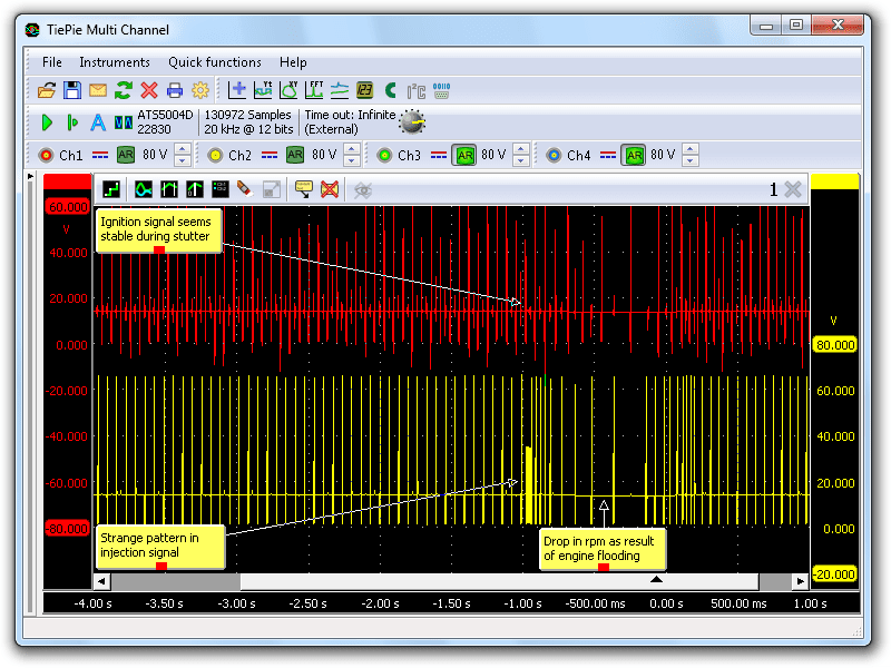
Figure 1 shows a measurement on the ignition signal (top) and an injector (bottom). This 6.5 second measurement shows many pulses in both signals. The larger distance between the pulses shows clearly that at some point the engine speed drops significantly. Right before the speed drop, a strange pattern with many pulses is visible in the injection signal causing the injector to be open much longer than required. This floods the engine, causing the mixture not to ignite and resulting in the drop of speed. After that, the engine restores to its original speed.
The selected measurement type on the automotive lab scope allows to zoom in at the strange pattern. In figure 2, the same signal is visible, now zoomed in so only 300 ms around the strange pattern is visible.
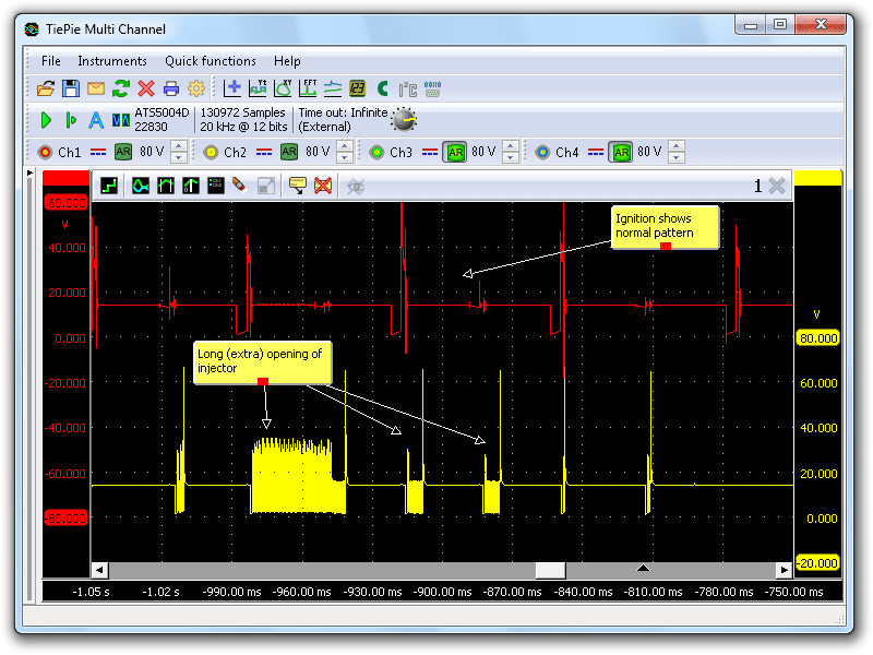
The ignition signal (top) is stable and remains stable during the problem moment. The injection signal (bottom) however clearly shows that the injector is opened for a long time and then twice for a shorter time. The pulsating pattern is used to limit the current through the injector to avoid that the injector coil becomes too hot. The pulses are too short to cause the injector to close again.
Next to find out is why the injector is opened this long? When accelerating a car, an injector is usually opened longer to allow more fuel to enter the cylinder. Acceleration information is collected by the ECM from the throttle position sensor and the Mass Air Flow sensor.
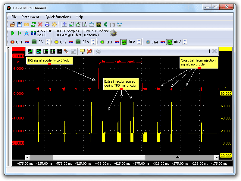
Next, the Throttle Position Sensor (TPS) signal (top) and the injection signal (bottom) were measured, the measured signals are shown in figure 3. The TPS signal jumps to 5 V, the maximum value for this sensor. The ECM responds as expected: the injectors are driven more and longer. Although it is just a short, 100 ms disturbance, it has a significant effect on how the engine runs.
When a sensor output signal suddenly jumps to the maximum value, this is usually not caused by the sensor itself, but by a wiring problem to the sensor. Usually the ground connection is broken, causing the output voltage to go to maximum. The ground connection of the sensor was tested by measuring the voltage between ground connector of the sensor and the ground of the battery. However, the ground signal remained at 0 V during the problem situation, so the problem was not caused by a defective ground connection.
Cause
When the ground connection is in good order only a few options remain:
- a short circuit between sensor power and sensor output, this requires the isolation of the two wires to be open
- a bad contact inside the connector of the sensor
- a defective ground connection inside the sensor
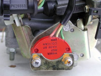
The first two options can be checked easily and no problems were found here, leaving only the third option. The sensor was replaced and the problem was gone.
Conclusion
A good automotive oscilloscope like the Automotive Test Scope ATS5004D can save a lot when diagnosing a problem in a car. The manually triggered long measurement proves to be very useful in finding the problem: simply drive the car until the problem occurs, press the Manual trigger button and the signals are captured, even from before pressing the button. The high zoom factor allows to focus on the smallest details. This relative short disturbance would have been hard to find without an automotive lab scope, because it is much to short to be seen on a multimeter. Only by keeping replacing components one by one, this problem might have been solved. A very ineffective and expensive method.
R. Metzelaar


