Vehicle information
| Brand: | Ford |
| Model: | F150 |
| Year: | 1998 |
| Engine: | 5.4L V8 |
| Cylinder count: | 8 |
| Fuel type: | Petrol |
| Motor management system: | EEC V |

Used equipment
Automotive Test Scope ATS5004D
4 channel automotive oscilloscope with differential inputsCurrent clamp TP-CC80
0 - 80 A input rangeThe Automotive Test Scope ATS5004D is in this article also referred to as automotive oscilloscope, as diagnosis oscilloscope and as lab scope.
Problem description
A Ford F150 with a 5.4 liter V8 engine was brought in with an ignition coil problem. This engine has a separate ignition coil for each cylinder, controlled directly by the ECM. One of the coils (each time of the same cylinder) would go defective after about half an hour driving. The coil was already replaced twice by a new one, cables, connectors and spark plugs were thoroughly checked, but nothing was found.
Measuring the ignition coil signals
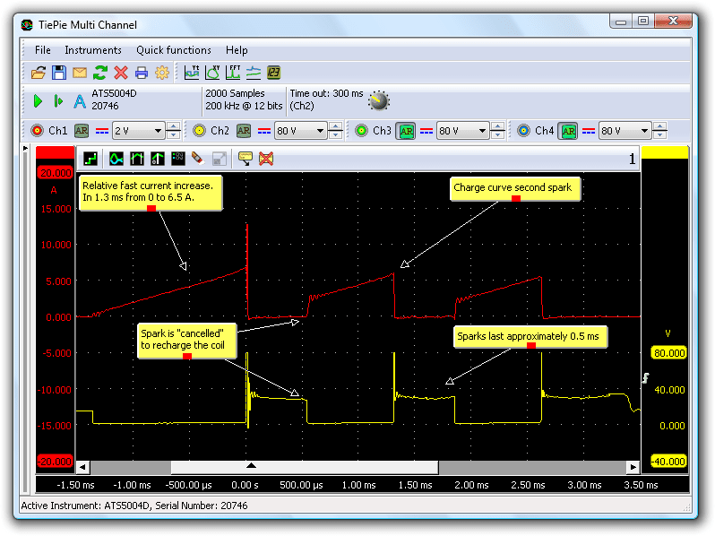
ATIS includes a predefined setup for measuring ignition signals with the automotive oscilloscope A current clamp on channel 1 is used to measure the primary ignition coil current. Channel 2 is measuring the voltage over the primary ignition coil terminals. A measurement on a good functioning ignition coil shows that this ignition system uses three sparks per cycle, see figure 1.

The purpose of such a 3-sparks ignition system is to provide a better combustion and better emission results. Within 3.5 milliseconds, each ignition coil has to generate three sparks. Each spark lasts approximately 0.5 ms. This requires a powerful ignition system, where the charging time for the coil should be very short. Charging time in this situation is only 0.7 ms. The first two sparks are "canceled" which results in energy remaining in the coil. This can be seen in the current jump for the second and third spark.
Problem located
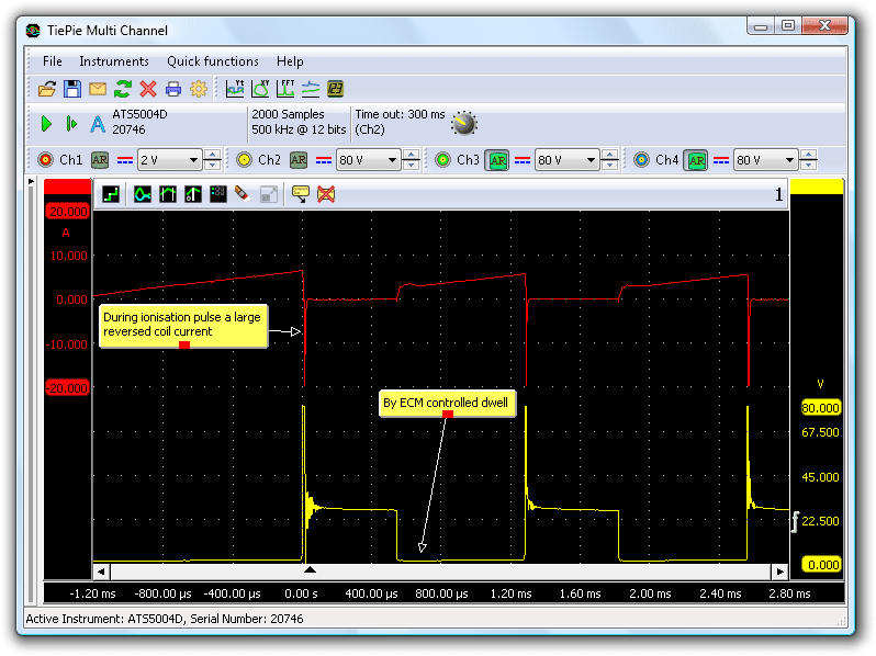
The same measurement was repeated on the cylinder with the ignition coil that had been replaced several times already. This measurement showed a different pattern: a large negative current flows through the coil at the moment the normal current is cut through the ECM.

The diagnosis oscilloscope was set to a 20 A range, the actual current was probably significantly higher than that.
Solution
Normally, an ignition control system is designed to have only positive current. In this situation, a negative current was flowing, in just one of the eight ignition coils. Since the ignition coils are driven directly by the ECM, it is very likely that this specific output of the ECM is defective. To test this, a large diode was placed in series with the ignition coil, blocking the negative current. With the diode added, the ignition coil no longer broke down. The negative current flowing through the coil was the culprit, causing the coil to break down rapidly. The garage was advised to replace the ECM.
Conclusion
In many cases, with components like injectors and ignition coils, measuring a voltage over a component will not reveal the problem. Measuring the current through the component will show a lot of extra information that can lead to the correct diagnosis. A current clamp is a useful tool for measuring a current, as it can be connected directly to the automotive oscilloscope and clamped around the conductor through which the current flows. The current can be measured while the circuit can remain intact.
R. Metzelaar


