Vehicle information
| Brand: | Kia |
| Model: | Carens |
| Engine: | 1.6 L |
| Engine code: | A6 |
| Cylinder count: | 4 |
| Fuel type: | Petrol |
| Motor management system: | Bosch Motronic 7.9.1 |
Used equipment

Automotive Test Scope ATS5004D
4 channel automotive oscilloscope with differential inputs
Measure lead TP-C1812B
low noise differential BNC to banana measuring lead, 3 m
Back Probe TP-BP85
thin and flexible back probeThe Automotive Test Scope ATS5004D is in this article also referred to as automotive oscilloscope, diagnosis oscilloscope and lab scope.
Introduction
Modern cars have sophisticated engine management systems that continuously monitor the functionality of all components. When a component operates outside specifications, an error code indicating the problem is generated and stored in an error log in the Electronic Control Module (ECM). When the error is severe a dashboard light will go on to inform the driver that service is required. The service engineer uses an error code scanner to read the stored errors from the car. The error code is then used to determine the problem component in the car and fix it accordingly.
However, the error generated by the motor management system is not always pointing to the cause of the problem. In some cases it just indicates a result of the problem. Finding the actual problem then requires further diagnosing, using the proper tools, like an automotive lab scope.
Problem description
A Kia Carens with 1.6 liter engine keeps generating an oxygen sensor (or lambda sensor) related code that the fuel mixture was too rich. Resetting the error and driving the car would set the error code again. Several components were replaced, even the ECM, but the error kept coming back. To solve this problem, different diagnosis techniques were required, using tools that give a proper insight what is actually happening. An automotive lab scope like the Automotive Test Scope ATS5004D is the right instrument to reveal that information.
Background information
An oxygen sensor (or lambda sensor) detects the presence of oxygen in the exhaust. When the fuel mixture is rich, no oxygen is found in the exhaust and the sensor output is about 0.8 V. When the engine runs lean, there will be oxygen present in the exhaust and the sensor output is 0.1 V. The ECM uses the oxygen sensor signal in combination with the amount of air entering the cylinders and the engine temperature to determine how much fuel needs to be injected for optimal combustion. In practice, the sensor signal will continuously toggle between 0.1 V (lean) and 0.8 V (rich), indicating that the ECM is controlling the engine close to the optimal fuel air ratio.
Measuring
Since the error code points to the oxygen sensor, this sensor was first measured. When idling, the signal toggled perfectly between rich and lean, indicating the ECM was able to create optimal combustion. When driving the car, the signal changed to a predominantly rich signal. The output signal levels of the sensor were correct and when idling, it would also toggle between the two levels as expected, indicating that the oxygen sensor was working well.
With a proper functioning oxygen sensor indicating a rich fuel mixture, there must be another component causing the fuel mixture to be rich. Two other signals used by the ECM to determine the proper mixture are the Mass Air Flow sensor (MAF) and the coolant temperature sensor. The MAF sensor was measured next.
ATIS contains a MAF sensor measurement that sets up the oscilloscope with one single click. It even loads a reference signal of a good functioning MAF sensor. This MAF sensor reference signal is measured using a specific procedure:
- Switch the key on
- After 5 seconds, start the engine and let it idle
- After again 5 seconds, rev up to 3000 rpm
- After another 15 seconds, release throttle and go back to idle
- After 5 seconds more, snap the throttle to wide open and let the engine return to ide
A measurement was performed on the MAF sensor, following this procedure. This makes it possible to compare different aspects of the signals. The measurement is shown in figure 1.
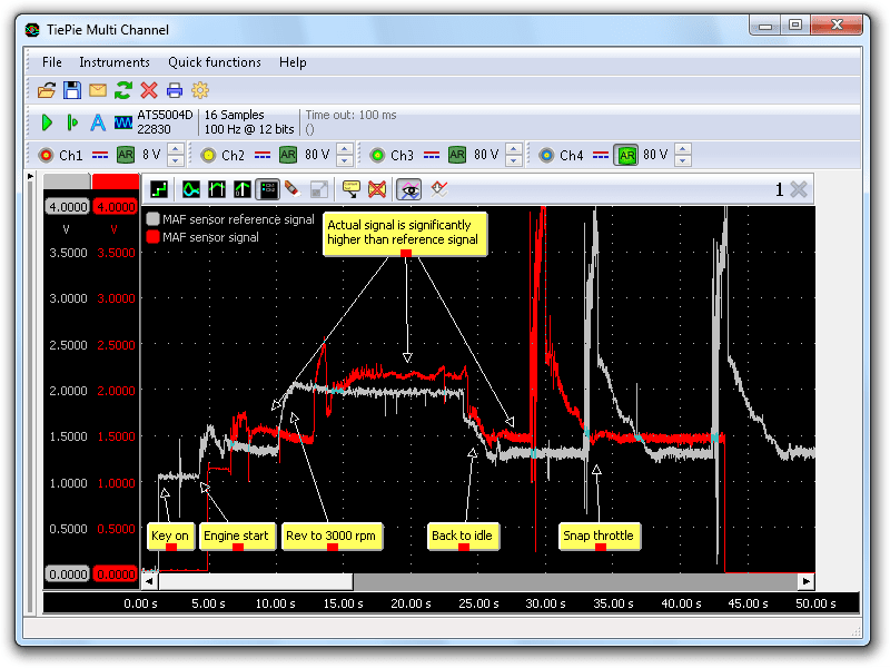
Although the timing of the actual sensor signal is not identical to the reference signal, the various parts are easily recognized. What immediately attracts attention is that the signal levels for the actual signal are significantly higher than the reference signal. Higher signal levels can indicate a malfunctioning or a dirty MAF sensor, but it can also indicate a grounding problem. If the grounding is not good, there will be a voltage drop over the ground connection, causing the output signal of the sensor to become higher. A next measurement was performed to test the ground connections of the MAF sensor and the ECM, the results are shown in figure 2.
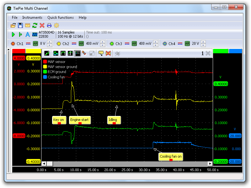
Channel 1 (red) shows the MAF sensor signal, channel 2 (yellow) the MAF sensor ground and channel 3 (green) the ECM ground. The two ground signals are both measured between battery negative and the sensor/ECM ground terminal, showing the actual voltage drop. Channel 4 shows the power supply of the cooling fan, which was used as extra load, to see the effect of a higher current on the ground voltage drop. When the engine is idling, the ground voltage drops for both the ECM and the MAF sensor are almost 0.1 V. Voltage drops larger than 0.1 V are too high and reason to reject a ground connection. Once the cooling fan is switched on, the ground voltage drop raises above 0.1 V, both for the MAF sensor ground and the ECM ground. The MAF sensor output signal also shows an increase when the fan is switched on.
Cause and Solution
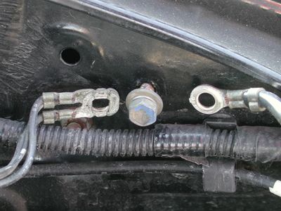
As the ground of the ECM also shows the voltage drop, the bad connection must be in the ECM grounding. The ground connections were inspected and one connection from ECM to ground appeared bad. The connection was taken apart, cleaned and installed again. The voltage drops were completely gone now.
To verify the repair, the MAF sensor measurement was repeated. This time the MAF sensor signal levels were exactly the same as the reference signal. No error codes were stored again.
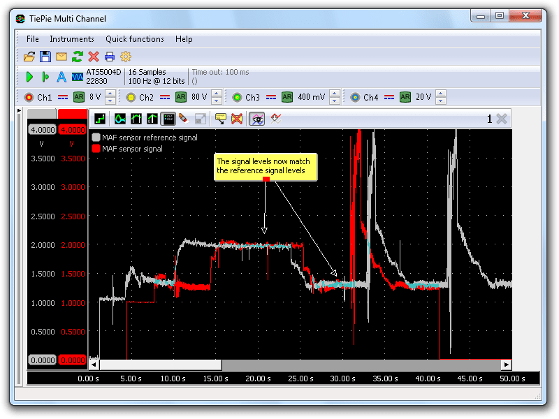
Conclusion
Due to the voltage drop in the ground connection, the MAF sensor generated a higher output signal. A higher MAF sensor signal means more air entering the cylinder, requiring more fuel for optimal combustion. In this case, the MAF sensor signal is too high, causing the ECM to think that more air enters the cylinder than actually does, which results in too much fuel to be injected. The excessive amount of fuel causes the mixture to be continuously rich, which was detected by the oxygen sensor, resulting in an error code.
Measuring with the Automotive Test Scope ATS5004D showed that the oxygen sensor was working fine and the problem had to be found elsewhere in the system. In the end, it turned out that one small connection caused all these problems.
R. Metzelaar